As defined in the IEEE-1588 standard, Precision Time Protocol (PTP) is a highly accurate method to synchronise computers over a Local Area Network (LAN). A Network Time Server using PTP is commonly referred to as an ‘IEEE-1588 Grandmaster’ or ’PTP Grandmaster’.
PTP Applications
Both Network Time Protocol (NTP) and Simple Network Time Protocol (SNTP) are popular methods to synchronise clocks across a Local Area Network (LAN) with accuracy to the millisecond range. Greater precision is required however in many industrial applications of time synchronisation. Wherever processes require that level of accuracy, such as within automation and control systems, measurement and automatic test systems, power generation, transmission and distribution systems, and telecommunications, Precision Time Protocol (PTP) is the solution.
Time Synchronisation and PTP Accuracy
Time synchronisation across a network requires both a master clock and at least one slave clock. Usually driven by a GPS receiver or external radio clock, a master clock is responsible for synchronising time across all slave clocks connected to it. A slave clock is a device in which a time signal terminates; it requires a connected master clock to maintain synchronised and accurate time, but it doesn’t distribute that time signal to any other device. Your network may also contain additional transmission components such as Ethernet switches with boundary clocks. These operate initially as a slave clock as they receive the time signal from the master clock, and then as a master clock as they distribute the time signal to all connected slave devices. As each slave will be synchronised to the master clock in terms of time, frequency and phase, it will therefore be synchronised with all other slave devices.
In the simplest form of time synchronisation, a master clock sends a message containing its time value to all connected slave clocks. As each slave clock receives the master clock value, they simply recalibrate their own clock to match it. However, this basic process doesn’t account for propagation delays in the Ethernet path affecting the time it takes to send the message, or any further impediments caused by processor queuing, IP message creation and latency. This creates a situation where the message might not accurately reflect the correct time when it is received by the slave. PTP compensates for these issues, determining any inherent delays in the process by sending protocol messaging between PTP nodes.
The Fundamentals of PTP Synchronisation
PTP operates similarly to Network Time Protocol (NTP), by defining synchronisation messages used between a master and a slave clock. Contained within the protocol are various elements, including the master sync message, master delay response message and slave clock delay request messages.
Both master and slave clocks capture precise timestamps of network activity. Using these timestamps, network latency is measured so that slave clocks can be precisely synchronised with the master. The master clock commonly transmits a sync message at two second intervals, whilst the slave unit typically transmits one delay request message a minute.
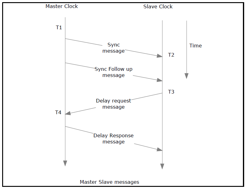
In order to determine the slave offset calculation, four timestamps are captured for activities between the slave and master clock. These timestamps, often referred to as T1, T2, T3 and T4, are displayed in the diagram below.

Two separate delay values must be determined: the delay from the master to slave, and from the slave to master.
To calculate the delay from the master to slave:
T1 is the initial timestamp, and is the exact time the sync message is sent by the master. Since T1 is an accurate recording of when the sync message was transmitted via the Ethernet port, it is sent in the follow-up message.
T2 is the second timestamp, and is the exact time the slave receives the sync message.
Once both T1 and T2 are available at the slave, the delay value between the master and the slave can be determined through the calculation T2 – T1.
To calculate the delay from the slave to the master:
T3 is the third timestamp, and is the exact time the delay request message is sent from the slave. T4 is the fourth and final timestamp, and is the exact time the master receives the delay request message.
Once both T3 and T4 are available at the slave, the delay value between the slave and the master can be determined through the calculation T4 – T3.
Once both the master to slave, and slave to master differences are available at the slave, the one-way delay can be determined. One-way delay = (master to slave difference + slave to master difference) / 2
An offset value is then calculated to adjust the slave clock:
Offset = master to slave difference – one-way delay
This can be simplified as:
Offset = ((T2 - T1) - (T4 - T3)) / 2
By utilising this offset, the slave clock can adjust its time to ensure it matches the master clock.

